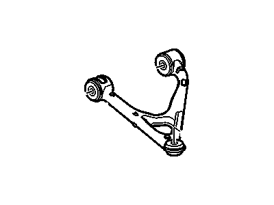
Loosen the wheel lug nuts, raise the vehicle, and support it securely on jackstands while blocking the front wheels to prevent rolling, then remove the wheel. Support the lower control arm with a jackstand and disconnect the ABS sensor connector along with the electronic suspension sensor link from the control arm. Loosen the upper balljoint nut, use a balljoint removal tool to separate the ballstud from the upper control arm, and remove the balljoint nut. Remove the upper control arm-to-subframe fasteners, noting the location of spacers/washers on models with specific option codes, and then take out the upper control arm from the vehicle. Installation is the reverse of removal, ensuring fasteners are tightened to the specified torque, and for models without certain option codes, raise the lower control arm with a floor jack to simulate normal ride height before tightening. Check and adjust the wheel alignment if necessary. For 2004 and earlier models, place a floor jack under the end of the transverse leaf spring attached to the lower control arm, disconnect the stabilizer bar link, measure the distance between the control arm and the spring at the bolt, and record it for installation. Remove the spring-to-control arm bolt, lower the control arm to release tension from the spring, and disconnect the electronic ride control suspension position sensor link if equipped. Detach the stabilizer bar link, remove the shock absorber-to-lower control arm nut/bolt, loosen the lower balljoint nut, and separate the ballstud from the knuckle. Mark the inner pivot bolt cam washer-to-subframe relationship, remove the control arm-to-subframe nuts/bolts, and detach the arm from the vehicle. For installation, follow the reverse of removal, ensuring alignment marks are matched, and raise the lower control arm with a floor jack before tightening. Check and adjust the wheel alignment if necessary. For 2005 and later models, support the lower control arm with a floor jack, disconnect the electronic ride control suspension position sensor link if equipped, detach the stabilizer bar link, remove the shock absorber lower mounting bolt, loosen the lower balljoint nut, and separate the balljoint from the rear knuckle. Remove the lower balljoint nut and lower the floor jack to release tension from the transverse leaf spring, mark the position of the lower control arm adjustment cams, and remove the bolts attaching the lower control arm to the subframe. For installation, reverse the removal steps, ensuring alignment marks on the cam bolts and subframe are lined up, tighten all fasteners to the specified torque, and raise the outer end of the control arm with a floor jack before tightening. It's advisable to check and adjust the wheel alignment after completing the job.