Make sure this part fits

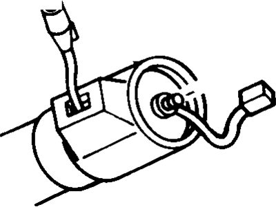
GM 26042978 F, Column A

1994 GM

Customer Questions & Expert Answers (3)
GM 26042978 F, Column A
  • Part Description
    F, Column A
  • Manufacturer
    General Motors
  • Manufacturer's Notes
    This part is discontinued.
Make sure this part fits
  • Related Parts
  • Product Specifications
  • Vehicle Fitment
  • Customer Questions & Expert Answers
  • Product Specifications

    BrandGenuine GM
    Manufacturer Part Number26042978
    Part DescriptionF, Column A
    Other NamesSteering Column
    ConditionNew
    Fitment TypeDirect Replacement
    ManufacturerGeneral Motors
    SKU26042978
    WarrantyThis genuine GM part is guaranteed by GM's factory warranty.
    Shipping & ReturnShipping Policy Return Policy
    Warning: California's Proposition 65
  • Vehicle Fitment

    Year Make Model Engine Important vehicle option details
    1994 Buick Century4 Cyl 2.2L, 6 Cyl 3.1LCUSTOM, CUSTOM STATION WAGON, SPECIAL 4 DOOR, SPECIAL STATION WAGON
    1994 Oldsmobile Cutlass4 Cyl 2.2L, 6 Cyl 3.1LS 4 DOOR, S STATION WAGON, SL 4 DOOR, SL STATION WAGON
  • Customer Questions & Expert Answers

    Q:
    I would like to confirm if this is the correct part number for my vehicle. Please advise. Thank you. Posted by GMPartsGiant Specialist
    A:
    You can Select Your Vehicle to check if 26042978 fits your vehicle.
    Posted by GMPartsGiant Specialist
    Q:
    How to disassembly and reassemble the standard version steering column on Oldsmobile Cutlass? Posted by Customer
    A:
    Remove the four screws securing the dash panel bracket to the steering column and retain the bracket to prevent damage to the mounting capsules. Secure the column in a vise by gripping one set of the weld nuts. Remove the directional signal switch, lock cylinder, ignition key warning switch, and ignition switch. For column shift models, drive out the upper shift lever pivot pin and remove the shift lever. Take out the upper bearing and thrust washer, then remove the four screws attaching the directional signal switch and ignition lock housing to the jacket, followed by the housing assembly. Extract the thrust cap from the lower side of the housing and lift the ignition switch actuating rod and rack assembly along with the shaft lock bolt and spring assembly from the housing. Remove the shift gate and the ignition switch actuator sector through the lock cylinder hole by pushing on the block tooth sector with a rod or punch. Remove the gearshift lever housing and shroud or the transmission control lock tube housing and shroud as applicable, then take out the shift lever spring from the gearshift housing or the lock tube spring as applicable. Pull the steering shaft from the lower end of the jacket assembly and remove the back-up switch or neutral safety switch using two screws. Remove the lower bearing retainer, and for automatics and floor shifts, take out the lower bearing retainer, adaptor assembly, shift tube spring, and washer, then press out the lower bearing by applying pressure to the outer race and slide out the shift tube assembly. For column shift with manual transmission, remove the lower bearing adaptor, bearing, and first/reverse shift lever, then press out the lower bearing by applying pressure to the outer race and remove three screws from the lower end bearing before sliding out the shift tube assembly. From the upper end of the mast jacket, remove the gearshift housing lower bearing. Replace any worn components and begin reassembly by applying a thin coating of lithium soap grease to all friction surfaces, then install the sector into the turn signal housing by reaching through the lock cylinder hole and placing the sector onto the shaft with a blunt tool. Install the shift gate onto the housing, insert the rack preload spring into the housing from the lower end, and assemble the locking bolt to the crossover arm on the rack. Insert the rack and lock bolt assembly into the housing with the teeth facing upwards, aligning the first tooth on the sector with the first tooth on the rack. Install the thrust cup into the housing, then install the gearshift housing lower bearing, ensuring alignment with the jacket's indentations and projections. Install the shift lever spring into the housing, then attach the housing and shroud assemblies onto the mast jacket, rotating slightly for proper seating in the bearing. With the shift lever housing in position and the gearshift housing at 'park', pull the rack downwards and install the directional signal switch and lock cylinder housing onto the jacket, securing it with four screws. Press the lower bearing fully into the adaptor assembly, and for automatics and floor shifts, assemble the spring, lower bearing, and adaptor assembly into the bottom of the jacket, holding the adaptor in place while installing the lower bearing reinforcement and retainer, ensuring the retainer snaps into the slots. For column shift with manual transmission, loosely install three screws in the jacket and shift tube bearing, assemble the first/reverse lever, and lower bearing and adaptor assembly into the bottom of the jacket, holding the adaptor in place while installing the bearing reinforcement and retainer, ensuring the retainer snaps into the slots, then place a 0.005 inch shim between the first/reverse lever and spacer, turn the upper shift tube bearing down, tighten the three screws, and finally remove the shim. Install the neutral safety or back-up switch, slide the steering shaft into the column, and install the upper bearing thrust washer. Install the ignition key warning switch, directional signal switch, lock cylinder assembly, and ignition switch. Finally, install the shift lever and shift lever pivot pin, then remove the assembly from the vise and torque-tighten the four dash bracket to column screws.
    Posted by GMPartsGiant Specialist
    Q:
    How can steering column components be serviced without removing the steering column, and what precautions should be taken during removal on Oldsmobile Cutlass? Posted by Customer
    A:
    Som of the steering column units can be repaired without detachment of the steering column but great care is needed at times of removal due to the built-in energy management. Don not hammer, drop, lean or jar the assembly it is necessary to use only factory installed fasteners or similar type screw or bolts as the wrong size may alpine compression if impacted. First remove the negative battery terminal bolt then use the correct puller to pull out the steering wheel. In the engine compartment disconnect the flanged end of the steering shaft at the flexible coupling and pull it away from the lower end of the steering column. On the lower end, remove the shift control linkage and indoors remove all electrical connections including main ignition connection, connection of the neutral-start and back-up lamp switches as well as pulling any connected wire from any clips. Take out all the screws which hold the column plate to the floor pan, and release the column from its location on the dashboard which may call for removal of additional trim to expose the nuts. If the shift position indicator is mounted, it should be disconnected, the seat should be pulled back as far as possible to provide enough room and when extending the column through the opening, it would be easier with help. As for assembly, place the column in the position in the vehicle, feed the lower end through the firewall, loosely insert the dashboard attaching nuts to support the tumblers, reconnect all of the electrical connections, and connect the lower end to the steering linkage, tightening the fasteners to the prescribed torque. Replace the shift linkage at the lower end, ensure that the column plate seal fits properly over the column plate, fix the steering column firmly to the floor pan, tighten the dashboard attaching screws, fix the transmission shift indicator, if exists, fix the trim panel and ashtray if removed and last fix the battery cable. Lift the front end and see that the steering wheel turn round and round without any hindrance to enable one ascertain that the flexible coupling has not been misshapen.
    Posted by GMPartsGiant Specialist
    If you have any questions about this product, please don't hesitate to ask us. We will be happy to help you!

Genuine GM Part 26042978, the Right Choice

To ensure reliability, purchase GM part # 26042978 F, Column A. It is sometimes referred to as GM Steering Column. Directly from GM, genuine parts are superb with regards to quality, longevity, and fit. Every single part passed stringent quality testing, so you can be sure that it's safe, durable, and built to perform like your original parts. This part fits specific Buick Century models. It fits Oldsmobile Cutlass.

GMPartsGiant.com is a leading supplier of genuine GM parts and accessories such as GM 26042978 F, Column A. You're certainly in the right place if you're searching for the great cost-effective OEM GM parts. Look no further than our vast inventory of genuine GM parts offered at unbeatable online prices, all of which are backed by the manufacturer's warranty. Not to forget, our hassle-free return policy and quick delivery service ensure a smooth shopping experience for you. For detailed Buick parts information, click here.

Why choose GM Parts Giant

  • Dedicated Service

    Your complete satisfaction is our #1 goal

  • Lowest Prices

    Best deals on genuine OE parts from dealerships

  • Fast Delivery

    Orders are processed and delivered promptly