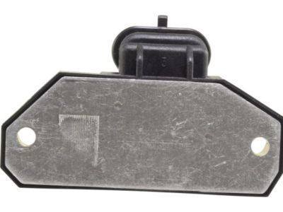
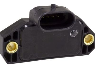
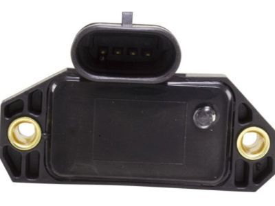
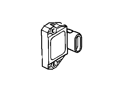
To check the High Energy Ignition System (HEI), start by disconnecting the four-terminal connector from the distributor and test for a spark at the coil using a spark tester connected to the coil wire. If there is a spark, inspect the distributor cap, rotor, and coil wire for any damage or opens. In case there's no spark, remove the distributor cap and reconnect the four-terminal connector to the ignition control module. Unplug the two-wire connector from the distributor and check for voltage at the module positive (+) terminal of the two-wire connector with the ignition switch turned ON. Depending on the reading, follow the diagnostic steps to identify potential faults and replace the faulty components as necessary.For the removal of the distributor, disconnect the negative battery terminal, remove the distributor cap and rotor, and disconnect the electrical connectors from the ignition control module. Remove both module attaching screws and lift the module away from the distributor. If reusing the same module, avoid wiping off the grease from the module or distributor base. For installation, apply silicone grease on the module face and distributor base if using a new module. Install the module, attach both electrical leads, and then reinstall the distributor rotor and cap. Finally, reattach the cable to the negative battery terminal.For Enhanced Distributor Ignition (EDI) System check, examine the crankshaft sensor reference voltage and resistance, and inspect the crankshaft sensor circuit for any issues. To remove the EDI ignition control module, detach the negative battery cable, disconnect the ignition control module electrical connector, remove both module attaching screws, and lift the module from its mount. For installation, secure the module with screws and plug in the electrical connector. Reattach the cable to the negative terminal of the battery.For Distributorless Ignition System (DIS) check, perform the ignition system checks first. Then, disconnect the two-wire electrical connectors from the ignition control module and verify battery voltage on the pink wire. Check the resistance of the crankshaft sensor and circuit. Also, check the output voltage signal from the crankshaft sensor. If all the tests pass but there is no spark output at any of the coils, the ignition control module may be defective. If any system check findings are incorrect, diagnose the individual circuits and components.To remove the DIS system, detach the negative battery cable, label and disconnect all spark plug wires from the DIS assembly, unplug the electrical connector at the module, and remove the DIS and support bracket assembly. Unbolt and separate the coil and module assemblies, then detach the wires between the module and coil assemblies from the spade terminals on the underside of the coils. Unbolt the module from the support bracket. Installation is the reverse of removal, ensuring the wires are attached to the new module's coil assembly spade terminals in the same order as removed.
")