My Garage
My Account
Cart
Genuine 1999 Oldsmobile Cutlass Steering Column
Steering Column Tilt- Select Vehicle by Model
- Select Vehicle by VIN
Select Vehicle by Model
orMake
Model
Year
Select Vehicle by VIN
For the most accurate results, select vehicle by your VIN (Vehicle Identification Number).
2 Steering Columns found
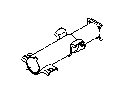
1999 Oldsmobile Cutlass Steering Column Jacket
Part Number: 26052372$6.33 MSRP: $145.02You Save: $138.69 (96%)Ships in 1-2 Business DaysProduct Specifications- Other Name: JACKET, Steering; Jacket
- Item Weight: 6.00 Pounds
- Item Dimensions: 19.2 x 10.0 x 6.2 inches
- Condition: New
- Fitment Type: Direct Replacement
- SKU: 26052372
- Warranty: This genuine part is guaranteed by GM's factory warranty.
- Product Specifications
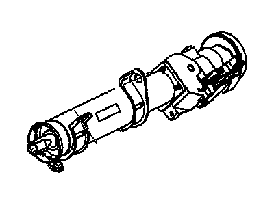
- Other Name: COLUMN, Steering; Column Assembly, Steering Column
- Item Weight: 11.70 Pounds
- Item Dimensions: 26.1 x 9.5 x 6.3 inches
- Condition: New
- Fitment Type: Direct Replacement
- SKU: 26050494
- Warranty: This genuine part is guaranteed by GM's factory warranty.
1999 Oldsmobile Cutlass Steering Column
We are your prime source for competitively priced and high-quality OEM 1999 Oldsmobile Cutlass Steering Column. We provide you with parts that will allow you to save a lot of money without sacrificing quality. All our OEM parts are backed by the manufacturer's warranty and shipped out at a swift rate.
1999 Oldsmobile Cutlass Steering Column Parts Questions & Experts Answers
- Q: How to dismantle and reassemble the Steering Column on 1999 Oldsmobile Cutlass?A: First, the shift lever of the standard version column has to be disassembled by the removal of the tilt release lever, the shift lever pivot pin and pulling out of the shift lever from the housing. First, locate the bracket that is holding the housing of the directional signal, and turn it on the anti-clockwise direction and remove the housing that is fixed with three screws. Place the tilt release lever and position the column up as far as it will go and then using a suitable flat-bladed screwdriver, unscrew the tilt lever spring retainer in an anti-clockwise direction to sit flush with the detent grooves in the housing. You need to first taken off the pot joint to steering shaft clamp bolt, then intermediate shaft and finally pot joint. To release the upper bearing inner race and seat, push in the upper shaft, to remove the bearing reinforcement, bearing and bearing adaptor assembly from lower end of the mast jacket, first, pry off the lower bearing retainer. Remove the upper bearing housing pivot pin using a suitable nut and bolt which passes through the holes. Install the tilt release lever back in place, unlock the lock shoes and meanwhile with the rack fully down and the housing being pulled upwards to detach the ignition switch rack from the initiator rod. Undo the bolts and take out the steering shaft assembly from the upper end of the column and also the upper bearing seat and inner race. Pull out the centering spheres and the anti-lash spring from the shaft and, if installed, unscrew the transmission indicator wire. Four screws holding the shaft bearing housing support and the housing support itself should be undone as well and the ignition switch actuator rod should also be pulled out. Suitably extract the shift tube from the lower side of the mast jacket and slide off the bearing housing support lock plate and by tilting it downwards remove the wave washer. Remove the shift lever housing or lock tube housing out of the mast jacket, wind up the shift lever spring with pliers then pull it out and make sure the spring plunger was removed especially in Floor change models. To leave the bearing housing, it is necessary to remove the opening shield of the tilt lever, then the lock bolt spring and the snap-ring from the sector driveshaft, and carefully tap the driveshaft from the sector. Tilt release lever, lever spring, driveshaft, sector, lock bolt, rack and, finally, the rack spring have to be taken out. Reduce pressure on the release lever by coaching the shoes inwards and sliding a buckle under the upper part of the shoes and the hull. Remove the lock shoe retaining pin and the lock shoe springs and observe the position of 4 slot shoe. should the bearings be replaced, the separator and balls should be taken out while the race to be driven out from the housing. Before assembling, a thin layer of lithium grease should be applied to those surfaces that react with the shaft; it is necessary to put the bearing into the housing very gently. Place the lock shoe springs, shoes, and shoe pin for the purpose of location by means of a suitable rod; put also the shoe release lever, spring, and pin. Fit the sector drive shaft loosely and secure it until the snap ring will go in and then lock the bolt on the sector cam surface so that the rack and spring sits firmly and has the block tooth engaging properly in the sector. Fit the tilt release lever and the lock bolt spring and apply torque to the retaining screw. After it, turn the shift lever spring with pliers clockwise and fit it into the seat, if you have the floor shift-fix the plunger at this place. Let the gearshift lever housing slide over the jacket on the steering mast, put in a wave-washer for the bearing support then lock plate has to be placed into the notches the jacket has. While doing so ensure that the shift tube is properly fitted on to the lower end of the mast jacket and that the keyway in the tube will mesh with the key in the shift lever housing, where possible, use GM tool number J23073 or similar. Screw in the outer nut until the shift tube is pulled into the housing, do not apply force at the end of the shift tube and the shift tube lever should be in line the slotted opening. Install the bearing support thrust washer and the bearing support retaining ring and then the bearing support, be sure the arrow 'V' in the support faces the arrow 'V' in the jacket, torque the support lock plate screws in M8. Insert the lower bearing adapter into the lower end and align the notches of the jacket, install the lower bearing, the bearing reinforcement and the retainer should fit the slot. Place the centering spheres and anti-lash spring in the upper shaft and then put in the lower shaft. Place the steering shaft assembly to the upper end of the shift tube, pass through it and the bearing. Fit the ignition switch actuator rod into the shift lever housing here, and extend the rack down from the housing. Position the bearing housing over the steering shaft with the rack engaging the free end of the actuator rod and locate the external release lever and the lock shoes in the release position while matabsing the bearing housing in place up to the time the pivot pin holes are correctly aligned, then the pivot pins are inserted. Put the bearing housing into the fully up position, fit the tilt lever spring guide, spring and the spring retainer and push the retainer into its hole and turn it clockwise until it fits into the housing properly. Fit in the upper bearing inner race and seat and the tilt lever opening shield. Pull out the tilt release lever and then fit in the directional signal housing and then tighten the three screws to the torque-limiting nut. Last is to set the tilt release lever and the shift lever, insert the pin of shift lever then the ignition key warning switch, the lock cylinder, directional signal switch, and the ignition switch. Place the grooves of the lower end of the pot along the steering shaft flat, fit the intermediate shaft assembly to the upper shaft, fit the clamp and bolt, and tighten it to the torque. Finally add the neutral safety or back-up switch and the four dash panel bracket to column screws with the slotted openings of the bracket facing the upper end of the column.


