My Garage
My Account
Cart
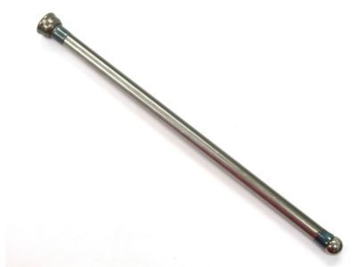
Genuine Cadillac Escalade Pushrod
Valve Push Rod- Select Vehicle by Model
- Select Vehicle by VIN
Select Vehicle by Model
orMake
Model
Year
Select Vehicle by VIN
For the most accurate results, select vehicle by your VIN (Vehicle Identification Number).
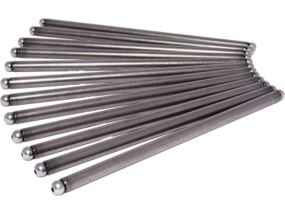
6 Pushrods found
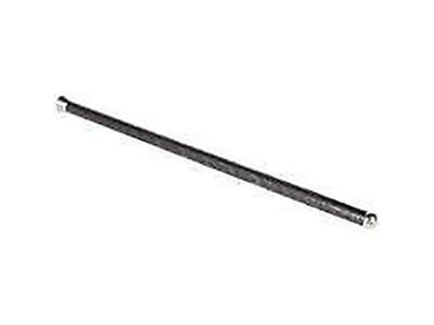
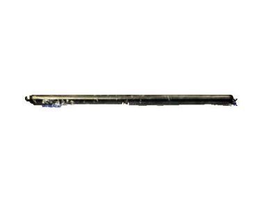
Cadillac Escalade Rod Assembly, Valve Push
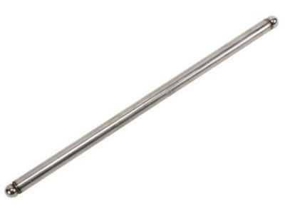
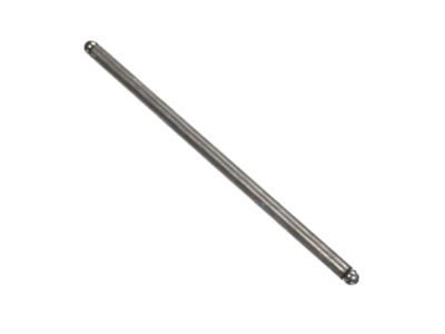
Part Number: 12619828$3.85 MSRP: $9.12You Save: $5.27 (58%)Ships in 1-2 Business DaysCadillac Escalade Rod,Valve Push
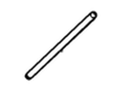
Part Number: 10238852$18.68 MSRP: $30.90You Save: $12.22 (40%)Ships in 1-2 Business DaysCadillac Escalade Rod,Valve Push
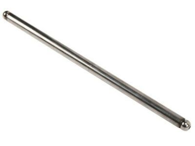
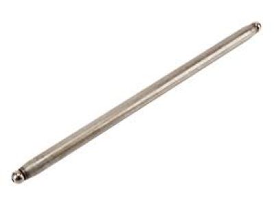
Part Number: 12556295$15.97 MSRP: $26.44You Save: $10.47 (40%)Ships in 1-2 Business DaysCadillac Escalade Rod Assembly, Valve Push
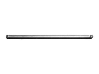
Part Number: 10241740$14.89 MSRP: $23.75You Save: $8.86 (38%)Ships in 1-3 Business DaysCadillac Escalade Rod,Valve Push
Part Number: 12556296$14.54 MSRP: $24.08You Save: $9.54 (40%)Ships in 1-2 Business Days
Cadillac Escalade Pushrod
Each OEM Cadillac Escalade Pushrod we offer is competitively priced and comes with the assurance of the manufacturer's warranty for the part. Furthermore, we guarantee the speedy delivery of your orders right to your doorstep. Our hassle-free return policy is also in place for your peace of mind.
Cadillac Escalade Pushrod Parts Questions & Experts Answers
- Q: How to remove and reinstall Pushrod and Rocker Arm in V8 engine on Cadillac Escalade?A:To have access to the valley of cylinder heads to remove valve covers, remove one at a time and take out the rocker arm along with the bolts and pedestal pivot support with the help of instruction to retain the position of components for reassembly. Pack each set of components in separate containers to prevent the overall organization of its parts and assembly of rocker arms and pivot support. Third, take out the push rods and keep them separately so as to prevent dropping of the correct push rods while fixing them. Both rocker arms for each cylinder should be checked for wear, external cracks and localised failure at contact points with pushrods and valve stems, and checks should be made for smoothness of facilities pivot bearings; if any bearing is in any way worn or damaged it will not be possible to re-use the complete rocker arm. Also, check for the cracks and damages on the rocker arm pivot support pedestal and also check the hole on the pushrod end of each rocker arm is not blocked. Check the pushrod for maximum wear past the ends and to the crank webs also check for cracks at the oil hole and if the hole is blocked, straighten them using a piece of plate glass. For installation, it is advisable to apply some drops of clean engine oil or assembling lobe on the lower end of every pushrod before laying it back into position; make sure each pushrod is properly seated in the lifter socket. Use engine assembly lube to coat the extended points of the stems of the valves and upper ends of the pushrods for the initial start up and paint cleaner engine oil on the rocker arm pivot shaft and bearing after which the rocker arms should be fitted to their original positions without tightening of bolts. Turn the crankshaft until the number one piston is at TDC on the compression stroke and both pushrod of number one cylinder will be in the downward position then tighten intake valve rocker arms for cylinder numbers 1, 3, 4, and 5 and exhaust for cylinder numbers 1, 2, 7 and 8 to torque specified. Turn the crankshaft through one revolution and tighten the intake valve R arms for No.2, 6, 7 and 8 and the exhaust valve R arms for No 3, 4, 5 and 6 to the torque specified above. Last, replace the valve covers with their respective bolts, start the engine and probe for queer valve train noises, and, inspect the valve covers gaskets for signs of leakage.
Related Cadillac Escalade Parts
Browse by Year
2024 Pushrod 2023 Pushrod 2022 Pushrod 2021 Pushrod 2020 Pushrod 2019 Pushrod 2018 Pushrod 2017 Pushrod 2016 Pushrod 2015 Pushrod 2014 Pushrod 2013 Pushrod 2012 Pushrod 2011 Pushrod 2010 Pushrod 2009 Pushrod 2008 Pushrod 2007 Pushrod 2006 Pushrod 2005 Pushrod 2004 Pushrod 2003 Pushrod 2002 Pushrod 2000 Pushrod 1999 Pushrod
