My Garage
My Account
Cart
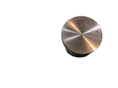
Genuine Chevrolet Express Piston
Engine Pistons- Select Vehicle by Model
- Select Vehicle by VIN
Select Vehicle by Model
orMake
Model
Year
Select Vehicle by VIN
For the most accurate results, select vehicle by your VIN (Vehicle Identification Number).
47 Pistons found
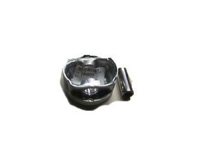
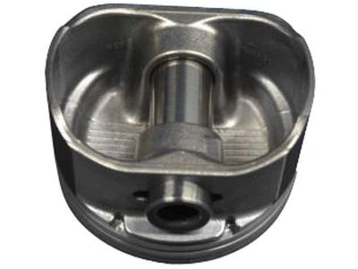
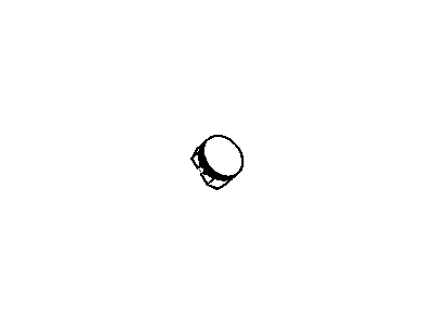
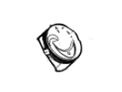
Chevrolet Express Piston Asm,(W/ Pinion & Retainer) (Std)
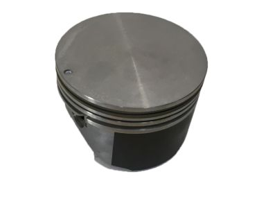
Part Number: 89017849$68.29 MSRP: $116.80You Save: $48.51 (42%)Ships in 1-2 Business DaysChevrolet Express Piston Asm,(W/ Pinion & Retainer) (0.5Mm Outside)
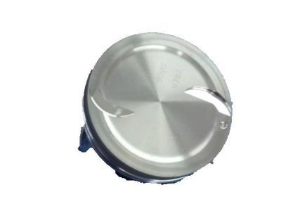
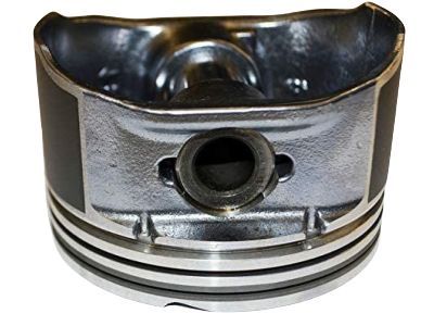
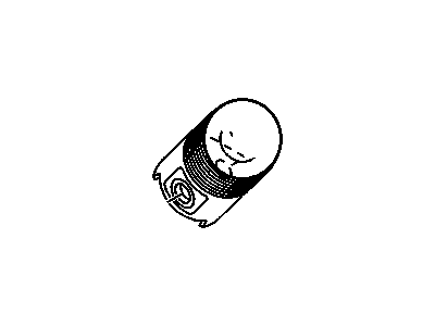
Part Number: 89017850$70.17 MSRP: $169.95You Save: $99.78 (59%)Ships in 1-3 Business DaysChevrolet Express Piston Asm,(W/ Pinion)
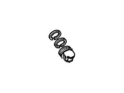
Part Number: 89060486$43.24 MSRP: $71.58You Save: $28.34 (40%)Ships in 1-2 Business DaysChevrolet Express Piston Kit (Standard)
Part Number: 19208675$45.20 MSRP: $74.83You Save: $29.63 (40%)Ships in 1-2 Business DaysChevrolet Express Piston Asm,(W/ Pinion)(Std)
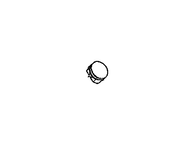
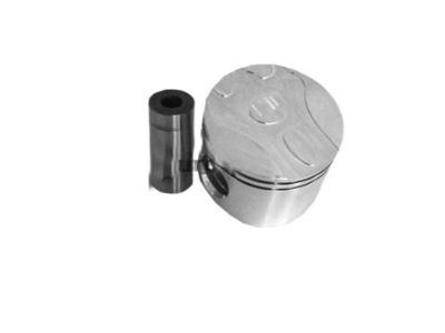
Part Number: 88894280$133.03 MSRP: $220.18You Save: $87.15 (40%)Ships in 1-3 Business DaysChevrolet Express Piston Asm,(W/ Pinion)
Part Number: 89060483$123.89 MSRP: $198.60You Save: $74.71 (38%)Chevrolet Express Piston Asm,(W/ Pinion)(0.127 Mm Outside)
Part Number: 88894281$110.92 MSRP: $223.69You Save: $112.77 (51%)Ships in 1-2 Business DaysChevrolet Express Piston Kit
Part Number: 12675714$47.14 MSRP: $78.00You Save: $30.86 (40%)Ships in 1-3 Business DaysChevrolet Express Piston Kit (Std)
Part Number: 12656878$48.13 MSRP: $79.67You Save: $31.54 (40%)Ships in 1-3 Business DaysChevrolet Express Piston Kit (0.5Mm Outside)
Part Number: 19208676$157.09 MSRP: $259.99You Save: $102.90 (40%)Ships in 1-3 Business DaysChevrolet Express Pin Kit,Piston
Part Number: 19302651$107.79 MSRP: $178.40You Save: $70.61 (40%)Ships in 1-3 Business DaysChevrolet Express Piston,Engine
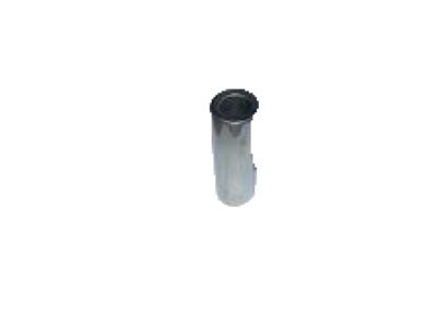
Part Number: 12550059$191.44 MSRP: $316.84You Save: $125.40 (40%)Ships in 1-3 Business DaysChevrolet Express Piston
Part Number: 97387004$161.32 MSRP: $254.96You Save: $93.64 (37%)Ships in 1-3 Business DaysChevrolet Express Piston, (W/Pinion)
Part Number: 12550062$186.00 MSRP: $307.86You Save: $121.86 (40%)Ships in 1-3 Business DaysChevrolet Express Piston Asm,(W/ Pinion)
Part Number: 19256946$25.75 MSRP: $40.51You Save: $14.76 (37%)Ships in 1-3 Business DaysChevrolet Express Piston, (W/Pinion, Std)
Part Number: 89017472$80.77 MSRP: $127.08You Save: $46.31 (37%)Chevrolet Express Piston Asm,(W/ Pinion)(Std)
Part Number: 19302143$110.32 MSRP: $173.58You Save: $63.26 (37%)
| Page 1 of 3 |Next >
1-20 of 47 Results
Chevrolet Express Piston
Each OEM Chevrolet Express Piston we offer is competitively priced and comes with the assurance of the manufacturer's warranty for the part. Furthermore, we guarantee the speedy delivery of your orders right to your doorstep. Our hassle-free return policy is also in place for your peace of mind.
Chevrolet Express Piston Parts Questions & Experts Answers
- Q: What steps must be taken before removing the piston and connecting rod assemblies on Chevrolet Express?A:Before these, one will have to strip down the cylinder heads and oil pan to get access to the piston and connecting rod assemblies. You should also occasionally look at the upper limit of ring travel, about 1/4 of an inch from the top of each cylinder, for any ridge; if there are ridges there due to carbon deposits or wear, they must be done away with using a ridge reamer to avoid causing the piston to break. Once the ridges have been taken off, position the engine in a way that the Crankshaft is vertically upward. The other is to compare the connecting rod endplay as measured by feeler gauges with the service limit of 0.005-015 inch; if greater than this limit, it may require new connecting rods. Locate the connecting rods and caps easily so that they are not confused and when loosening the connecting rod cap bolts or nuts, it is done progressively such that they can be overstated by hand. Take out the first connecting rod cap and the bearing insert without the insert falling off and push the connecting rod and piston assembly out from the top of the engine use the wooden or plastic hammer handle if possible. Perform this to the rest of the cylinders replacing the old rod cap bolts, if any, with new ones. Because of the tension between the joint and the bearing, if the caps and bearing inserts are removed it is advisable to replace them in their original positions as re-creating tension could damage them. Pistons and connecting rods are now available for inspection and rebuilding or replacement if necessary. When new piston rings are to be fitted, measure the ring end gaps, to ensure that the side clearance of the piston ring is correct. Specify the location and orientation of the piston/connecting rod assemblies and the new rings in order to match them again for assembly. Place the top ring above the first cylinder, align with cylinder bore walls and do an end gap measurement using feeler gauges adjusting as necessary. Make sure you fit the oil control ring first then the middle and finally the top ring making sure you have the correct side up. Do not install nitrided cylinders if the cylinder walls are contaminated, the top edge of each cylinder bored is not chamfered, and the crankshaft is not inserted into the cylinder. Scrape off the bearing surfaces of the connecting rod and cap and fit the new upper bearing insert, that must be a tight fit, but not stick, without using oil. Adjust the position of the ring with reference to the cylinder and lubricate the piston and rings, to compress the piston ring use a piston ring compressor. Place the piston/connecting rod assembly into the cylinder bore such that the piston faces the right way and then gently drive in the piston until it hits the bottom of the cylinder bore while at the same time aligning the connecting rod with the crankshaft journal. Measure the oil clearance of the connecting rod bearing using Plastigage after which the bearing faces should be clean and grease or assembly lube applied before final assembly. This will be followed by the same process for the other four OTR assemblies and make sure they are clean and properly oriented. Following installation, turn the crankshaft to inspect the corresponding amount of tightness or recheck the connecting rod's end float then resize, if needed.
Related Chevrolet Express Parts
Browse by Year
2024 Piston 2023 Piston 2022 Piston 2021 Piston 2020 Piston 2019 Piston 2018 Piston 2017 Piston 2016 Piston 2015 Piston 2014 Piston 2013 Piston 2012 Piston 2011 Piston 2010 Piston 2009 Piston 2008 Piston 2007 Piston 2006 Piston 2005 Piston 2004 Piston 2003 Piston 2002 Piston 2001 Piston 2000 Piston 1999 Piston 1998 Piston 1997 Piston 1996 Piston
