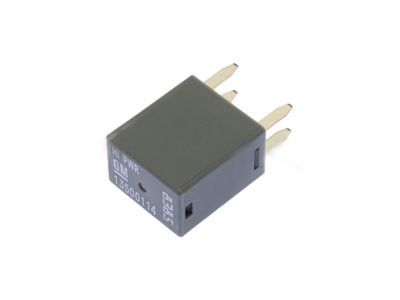
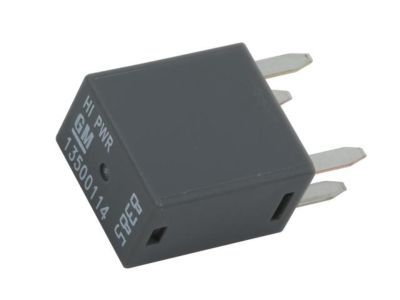
Make sure this part fits

Cadillac 13500114 RELAY ASM,ACSRY TIME DELAY CUTOFF *GRAY

1994-2024 Cadillac

Customer Questions & Expert Answers (39)
GM 13500114 RELAY ASM,ACSRY TIME DELAY CUTOFF *GRAY
  • Part Description
    RELAY ASM,ACSRY TIME DELAY CUTOFF *GRAY
  • Replaces
    12088567, 12135170, 19116057, 92199312, 12193606, 12135034, 19115080, 15328866, 15393412
  • Manufacturer
    General Motors
Make sure this part fits
$10.29 MSRP: $20.88
You Save: $10.59 (51%)
Ships in 1-2 Business Days
1
ADD TO CART
  • Related Parts
  • Product Specifications
  • Vehicle Fitment
  • Customer Questions & Expert Answers
  • Product Specifications

    BrandGenuine Cadillac
    Manufacturer Part Number13500114
    Part DescriptionRELAY ASM,ACSRY TIME DELAY CUTOFF *GRAY
    Item Dimensions3.8 x 2.1 x 0.7 inches
    Item Weight0.40 Pounds
    ConditionNew
    Fitment TypeDirect Replacement
    Replaces12088567, 12135170, 19116057, 92199312, 12193606, 12135034, 19115080, 15328866, 15393412
    ManufacturerGeneral Motors
    SKU13500114
    WarrantyThis genuine GM part is guaranteed by GM's factory warranty.
    Shipping & ReturnShipping Policy Return Policy
    Warning: California's Proposition 65
  • Vehicle Fitment

    Year Make Model Engine Important vehicle option details
    2013-2019 Cadillac ATS4 Cyl 2.0L, 4 Cyl 2.5L, 6 Cyl 3.6L2 DOOR COUPE, 2 DOOR LUXURY COUPE, 2 DOOR PERFORMANCE COUPE, 3 DOOR PREMIUM COUPE, 4 DOOR LUXURY SEDAN, 4 DOOR PERFORMANCE SEDAN, 4 DOOR PREMIUM SEDAN, 4 DOOR SEDAN, V-SERIES 2 DOOR COUPE, V-SERIES 4 DOOR SEDAN
    2004-2019 Cadillac CTS4 Cyl 2.0L, 6 Cyl 2.8L, 6 Cyl 3.0L, 6 Cyl 3.2L, 6 Cyl 3.6L, 8 Cyl 5.7L, 8 Cyl 6.0L, 8 Cyl 6.2L2 DOOR COUPE, 4 DOOR, 4 DOOR (RHD), 4 DOOR PERFORMANCE SEDAN, 4 DOOR PLUS SEDAN, 4 DOOR PREMIUM SEDAN, 4 DOOR RHD, 4 DOOR SEDAN, 4 DOOR SEDAN(RHD), 4 DOOR STATION WAGON, 4 DOOR STATION WAGON(RHD), 4 DOOR V-SERIES SEDAN, 4 DOOR WAGON, 4 DOOR WAGON(RHD), 4 DOOR(RHD), V 2 DOOR COUPE, V 4 DOOR, V 4 DOOR SEDAN, V 4 DOOR WAGON
    2006-2011 Cadillac DTS8 Cyl 4.6L4 DOOR, FUNERAL COACH, LIMOUSINE
    1996-2005 Cadillac Deville8 Cyl 4.6L4 DOOR, DEVILLE, HIGH LUXURY, SEVILLE, SLS, STS, TOURING 4 DOOR, TOURING SEDAN
    1996-2002 Cadillac Eldorado8 Cyl 4.6LELDORADO
    2015-2024, 2002-2012 Cadillac Escalade6 Cyl 3.0L Diesel, 8 Cyl 5.3L, 8 Cyl 6.0L, 8 Cyl 6.0L Flex, 8 Cyl 6.2L, 8 Cyl 6.2L Flex1/2 TON, 1500 4 DOOR, 1500 4 DOOR SUV, 1500 4 DOOR UTILITY, 1500 CREW CAB, 1500 CREW CAB STANDARD BOX, 3/4 TON, 3500 CREW CAB ONLY, 3500 CREW CAB STANDARD BOX, 3500 REGULAR CAB, 4 DOOR 1/2 TON, CLASSIC 1500 CREW CAB LONG BOX, CLASSIC 1500 EXTENDED CAB STANDARD BOX, CLASSIC 1500 REGULAR CAB LONG BOX, CLASSIC 1500 REGULAR CAB STANDARD BOX, CLASSIC 2500 CREW CAB LONG BOX, CLASSIC 2500 CREW CAB STANDARD BOX, CLASSIC 2500 EXTENDED CAB LONG BOX, CLASSIC 2500 EXTENDED CAB STANDARD BOX, CLASSIC 2500 REGULAR CAB, CLASSIC 3500 CREW CAB, CLASSIC 3500 EXTENDED CAB, CLASSIC 3500 REGULAR CAB, EXT 1/2 TON, EXT 3/4 TON, YUKON XL/DENALI XL/ESCALADE ESV, YUKON/DENALI/ESCALADE
    1994 Cadillac Fleetwood8 Cyl 5.7LBROUGHAM 4 DOOR
    2004-2016 Cadillac SRX6 Cyl 2.8L, 6 Cyl 3.0L, 6 Cyl 3.6L, 8 Cyl 4.6L4 DOOR, 4 DOOR(RHD), CROSSOVER 4 DOOR, SRX, V8 4 DOOR
    2005-2011 Cadillac STS6 Cyl 3.6L, 8 Cyl 4.4L, 8 Cyl 4.6L4 DOOR, 4 DOOR(RHD), V 4 DOOR
    1996-2004 Cadillac Seville8 Cyl 4.6L4 DOOR, DEVILLE, HIGH LUXURY, SEVILLE, SLS, STS, TOURING 4 DOOR
    View More
  • Customer Questions & Expert Answers

    Q:
    I am wonder if this is complete and correct part for my vehicle. Posted by GMPartsGiant Specialist
    A:
    You can Select Your Vehicle to check if 13500114 fits your vehicle.
    Posted by GMPartsGiant Specialist
    Q:
    How to Test and Troubleshoot Relays on Buick Enclave? Posted by Customer
    A:
    In the vehicle, various electrical accessories such as the fuel injection system, horns, starter, and fog lamps utilize relays to transmit electrical signals to their respective components. Relays work by using a low-current control circuit to open and close a high-current power circuit, enabling the proper operation of these components. Most relays can be found in the engine compartment and interior fuse/relay boxes. If a faulty relay is suspected, it can be tested using the following procedure or taken to a dealer service department or repair shop for evaluation. The relays used in these vehicles are typically ISO relays, adhering to International Standards Organization standards. They have numbered terminals indicating their circuit connections and functions. Two of the relay terminals are for the control circuit, connecting to the relay coil, while the other terminals serve as the power circuit. When energized, the relay's coil creates a magnetic field that closes the larger contacts of the power circuit, providing power to the circuit loads. Terminal 85 and 86 are usually the control circuit, with terminal 86 connected to battery positive (B+) voltage and terminal 85 to ground in relays with diode terminals. If the relay contains a resistor, terminals 85 and 86 can be connected in either direction with respect to B+ and ground. Terminal 30 is typically connected to the battery voltage source (B+) for the circuit loads, and terminal 87 is connected to the ground side of the circuit, either directly or through a load. Relays may have additional terminals, such as 87A, 87B, 87C, etc., for alternate load or ground connections. To test the relay, use an ohmmeter to check continuity through the relay control coil and ensure resistance matches the expected value. If the relay fails the tests or shows infinite resistance, it should be replaced. Additionally, when testing the relay's power circuit terminals, there should be no continuity between terminals 30 and 87 with the relay de-energized, but there should be continuity when the relay is energized using jumper wires. If any of the tests indicate a failure, the relay should be replaced.
    Posted by GMPartsGiant Specialist
    Q:
    What is the purpose of relays in electrical system on Buick Rainier? Posted by Customer
    A:
    Several electrical accessories in a vehicle, such as the fuel injection system, horns, starter, and fog lamps, use relays to transmit the electrical signal to the component. Relays have a control circuit and a power circuit, with the control circuit opening and closing the power circuit. If a relay is defective, the component will not function. Most are found in the engine compartment or fuse boxes. To test, remove and check it for continuity using an ohmmeter. The terminals of ISO relays are numbered to indicate their circuit connections and functions.
    Posted by GMPartsGiant Specialist
    Q:
    What role do relays play in the operation of electrical accessories on Cadillac CTS? Posted by Customer
    A:
    A number of components in the vehicle employ the use of relays to switch electrical signals to the parts and the following are some of them, the fuel injection systems, horns, starters and the fog lamps. A relay works on the principle of switching on and off of a low current path called the control circuit to switch on and off a high current path called the power circuit. Any malfunction or failure in the relay will mean that the pertinent component will also not function as it is supposed to. Generally, relays are affixed in the engine compartment and in the interior fuse and relay boxes.
    Posted by GMPartsGiant Specialist
    Q:
    How do electrical circuits utilize relays to transmit signals and what steps should be taken if a relay is suspected to be faulty on Cadillac Escalade? Posted by Customer
    A:
    Many electric circuits in the vehicle apply the use of relays to provide electrical signals to components, using a low-amp control circuit to regulate a high-amp power circuit. A defective relay will serve as an impediment to the optimum performance of the linked component; most of these relays are in the engine part fuse/relay container, while others are in the specialized interior fusable link override encompassing the fuse box in the dash. If a faulty relay is suspected, it can pulled out and examined using a particular method, or by a dealer service department or a repair shop, and a faulty relay must be in its entirety. Most of the relays used in the vehicles under analysis are ISO relays and they are numbered to illustrate the connections and the functions of the respective circuit; two typical configurations of terminals are present. The other terminals of the control circuit makes contact with the relay coil The power circuit makes contact with the other part of the coil making it provide magnetic field to close the larger contacts which supplies power to the circuits load. Speakers Terminal 85 and 86 are normally utilized for control circuit though additional connection is stipulated depending on the presence of diode or resistor. Terminal 30 is linked to the battery voltage supply while terminal 87 is linked to the device that is being supplied power with other terminals available as links for other connections. For checking the relay the continuity through the control coil can be checked using an ohmmeter and appropriately low resistance in one direction and high resistance in the other direction should be indicated if the latter is found to be of infinite resistance then it should be replaced. When the relay is unsoldered, there is no continuity between the terminals of the power circuit while there is continuity between terminals 30 and-when the circuit is energized and no continuity between these two terminals when the circuit is de-energized. Putting an end to this discussion, applying a fused jumper wire from the terminal number 86 and the positive terminal of Battery and another from number 85 to any ground point should make the relay click; the continuity between terminals number 30 and 87 should further be checked. Any testing would show that the relay had failed and it should then be changed.
    Posted by GMPartsGiant Specialist
    Q:
    What role do relays play in the operation of electrical accessories on Chevrolet Camaro? Posted by Customer
    A:
    In the vehicle, the electrical accessories including the fuel injection system, horns, starter, and fog lamps employs a relay to send the electrical signal to the concerned component. Relays work on a principle by which a low current circuit is used to switch on and off a high current circuit. In other words, when a relay is faulty the related component will not operate as required. All relays are arranged in the engine bay and compartment as well as interior fuse/relay boxes; the engine compartment fuse and relay panel is on right side of the engine compartment; the front interior fuse/relay box is behind the left end cap of the instrument panel and includes a fuse and relay card located on the back cover.
    Posted by GMPartsGiant Specialist
    Q:
    What role do relays play in the operation of electrical accessories on Chevrolet Cruze? Posted by Customer
    A:
    In the vehicle, relays are used in a number of electrical accessories such as the fuel injection system, horns, starter, and fog lamps where the relay is used to switch the electrical signal to the component. Relays work on the basis of a low current control circuit that can switch on and off a high current power circuit. When a relay is defective, it malfunctions and this affects the function of the corresponding component. Almost all relays are usually fitted in the engine bay fuse / relay box.
    Posted by GMPartsGiant Specialist
    Q:
    What role do relays play in the operation of electrical accessories on Chevrolet Corvette? Posted by Customer
    A:
    Some of the electrical accessories in the car the fuel injection system, horns, starter and fog lamps utilize relays to relay the electrical signals to the concerned part. A relay works by having a control circuit, a low current in this case, to switch on or off a power circuit which is high current. If we have a defective relay, the associated component will not operate as it is suppose to or not at all. As a rule, relays are installed in the engine compartment and in interior fuse and relay boxes.
    Posted by GMPartsGiant Specialist
    Q:
    How to test and diagnos a defective relay on Chevrolet Cobalt? Posted by Customer
    A:
    Several electrical accessories in a vehicle, such as the fuel injection system, horns, starter, and fog lamps, use relays to transmit the electrical signal to the component. Relays have a control circuit and a power circuit, and if a relay is defective, the corresponding component will not operate properly. Most relays are located in the engine compartment fuse/relay box, with some specialized relays found above the interior fuse box in the console. To test a relay, it can be removed and checked for continuity using an ohmmeter. The terminals of ISO relays, commonly used in these vehicles, are numbered to indicate their circuit connections and functions. Terminal 85 and 86 are typically the control circuit, with terminal 30 connected to the battery voltage source and terminal 87 connected to the component being powered. If the relay contains a diode or resistor, specific polarity and resistance values should be observed. If the relay fails any of the tests, it should be replaced.
    Posted by GMPartsGiant Specialist
    Q:
    How do relays function in electrical systems, and what steps should be taken to test and replace a defective relay on Chevrolet Express? Posted by Customer
    A:
    Quite a number of electrical accessories in the vehicle use relays to pass current to the component, and if the relay is faulty, then the specified component will not function as expected. That fuse is more often found in the engine compartment fuse and relay box, while some are found in the several wiring harnesses underneath the instrument panel. The suspected faulty relay can be readily withdrawn and checked using a certain procedure or may be referred to a dealer service department or a competent repair shop and since the relays come as assemblies or assemblies of required relays that have become faulty, they must be replaced as a whole. Many of the relays utilized in these automobiles are termed as "ISO" relays and bear numerical suffixes referring to their typical circuit connections/uses; the ISO relays essentially have two classic types of terminal arrangements. In order to find out which wires are connected in which manner, the wiring diagram for the circuit in question must be consulted, and in the absence of this information the following facts may be helpful. The two terminals on the right are for the relay control circuit and connected to the relay coil while the other two are of the power circuit. In the energised state of the coil, the larger contacts of the power circuit are closed to allow energy to flow to the circuit loads. The control circuit is usually terminals 85 and 86; if the diode is present the 86 must go to battery positive and 85 to ground if the resistor is present either end of terminal 85 or 86 can be connected. Terminal 30 is used to link the unit to the battery voltage to the circuit loads while terminal 87 connects to the ground side of circuits. Continuity checks can be done on relay control coil using an ohmmeter by placing leads on the meter in correct polarity then switch the sides of lead to check for continuity in the other direction. If a resistor is present, the resistance should be equal whether in forward or reverse polarity, if a diode is present then resistance should be higher in forward polarity. Thus if there is an infinite resistance in normal as well as in the auxiliary circuit, it call for replacement of the relay. Once the relay is removed continuity should be tested between the power circuit terminals, there should be no continuity from terminal 30 to 87 when the circuit is de-energized. If a fused jumper wire is connected to terminal 86 and the positive battery terminal and another end of the relay to pin 85 to ground the relay should click. When the jumper wires are connected, there should be continuity between terminal number 30 and 87. Where any of the above tests fail, the relay should be replaced.
    Posted by GMPartsGiant Specialist
    Q:
    What are the functions and testing procedures for relays on Chevrolet Impala? Posted by Customer
    A:
    Some of the electrical accessories found in a car include the fuel injection system horn-starter fog lamps and much more that use relays to pass electrical signals to them. Relays are devices which have a low current control circuit to switch a high current power circuit. A defective relay will cause the associated component not to work as it is supposed to work. Almost all the relays are fixed in the engine compartment fuse/relay box, but a few select relays are in the interior fuse box well above the dashboard. If a faulty relay is believed to exist, it must be removed, and tested by following some procedure or taken directly to a dealer service department or a repair shop and any faulty relay must be replaced in its entirety. In these vehicles, most relays are ISO relays; they have numbered terminals, giving information about typically used circuits and their functions, and two terminal configurations. The wiring diagram of the circuit might assist in pointing the right connections that have to be made for testing purposes. Two terminals of the relay are used in the control side of the coil while the other two terminals are found in the power side of the relay. Whenever it is energised, the coil produces a magnetic field to make the larger contacts of the power circuit close to supply power to the loads. The control circuit is usually formed by the terminals 85 and 86; if a diode is provided, the terminal 86 goes to the battery positive voltage, and the terminal 85-to the ground, and the resistor enables the terminals 85 and 86 are interchangeable. There is also another terminal to handle the rest of battery voltage for circuit loads identified as terminal 30 while terminal 87 is to where a component that is to be energized is to be connected while the other terminals that may be 87A, 87B and so on are the backup terminals. To confirm continuity through the relay control coil there is always the use of an ohmmeter which should ideally be checked with both polarities. But if a resistor is used, the resistance should be the same in each direction of operation while a diode Normally a diode will offer higher resistance in the forward polarity direction. Coil resistance of both first and second relays to zero and infinite indicating the relays should be replaced. When the relay is unscrewed and disconnected, continuity should be found between the power circuit terminals and at the same time, there should be no continuity found between terminal 30 and 87 when the circuit power connection is disconnected. By connecting a fused jumper wire to terminal 86 and the positive battery terminal, and another jumper wire between terminal 85 and the negative terminal of the battery the relay should make a clicking sound. With these connections, it should now be possible to establish continuity between terminals '30 and '87. In the case that the relay does not pass any of these tests, it is advised that it is replaced.
    Posted by GMPartsGiant Specialist
    Q:
    How do relays function in electrical systems, and what steps should be taken to test and replace a defective relay on Chevrolet Malibu? Posted by Customer
    A:
    There are so many electrical equipment fitted in the vehicle, which includes the fuel injection system, horns, starter and the fog lamps among others that use relay to in transmitting electrical signals to other components. Relays are controlled with an extremely small amount of current to open and close a large amount of power current, and if a relay is bad that means the related component will not work correctly. A vast majority of relays are installed in the engine compartment and interior fuse/relay boxes and if one believes that a certain relay is bad or failing, the relay should be removed and checked or taken to a dealer service department or auto electrical repair shop: in case of bad relays, these should be replaced as a package. These are mainly ISO relays which have digit symbols at their terminal to show their circuits and roles; they come in two types of terminal connection systems. The control circuit is usually connected to the relay coil whereas the other two terminals are connected to the power circuit. When energized the coil establishes a magnetic field that closes the large contacts of the power circuit to supply power to the loads. Terminals 85 and 86 are usually used in the control circuit but if a diode or resistor is incorporated then specific connections are necessary. Terminal 30 provides a connection to the battery voltage supply for the circuit loads and terminal 87 is connected to the ground side of the circuit. Using an ohmmeter one can check continuity through the control coil, and the must have the correct resistance figure in both directions: forward and backward, if the ohmmeter shows an infinite resistance, the relay should be replaced. When the relay is out, there should be no continuity between the power circuit terminals and there should be continuity only between terminal 30 and 87 when the MCB is de-energized. To check the relay the positive end of a fused jumper wire should be connected to terminal 86 and the negative end connected to the positive terminal of the battery while the other is connected to Terminal 85 to ground, the relay should click, and there should be continuity between terminal 30 & 87. In case of any test, which reveals that the relay has not worked, then such a relay has to be replaced.
    Posted by GMPartsGiant Specialist
    Q:
    What are the functions and testing procedures for relays on Chevrolet Monte Carlo? Posted by Customer
    A:
    Some of the electrical accessories found in a car include the fuel injection system horn-starter fog lamps and much more that use relays to pass electrical signals to them. Relays are devices which have a low current control circuit to switch a high current power circuit. A defective relay will cause the associated component not to work as it is supposed to work. Almost all the relays are fixed in the engine compartment fuse/relay box, but a few select relays are in the interior fuse box well above the dashboard. If a faulty relay is believed to exist, it must be removed, and tested by following some procedure or taken directly to a dealer service department or a repair shop and any faulty relay must be replaced in its entirety. In these vehicles, most relays are ISO relays; they have numbered terminals, giving information about typically used circuits and their functions, and two terminal configurations. The wiring diagram of the circuit might assist in pointing the right connections that have to be made for testing purposes. Two terminals of the relay are used in the control side of the coil while the other two terminals are found in the power side of the relay. Whenever it is energised, the coil produces a magnetic field to make the larger contacts of the power circuit close to supply power to the loads. The control circuit is usually formed by the terminals 85 and 86; if a diode is provided, the terminal 86 goes to the battery positive voltage, and the terminal 85-to the ground, and the resistor enables the terminals 85 and 86 are interchangeable. There is also another terminal to handle the rest of battery voltage for circuit loads identified as terminal 30 while terminal 87 is to where a component that is to be energized is to be connected while the other terminals that may be 87A, 87B and so on are the backup terminals. To confirm continuity through the relay control coil there is always the use of an ohmmeter which should ideally be checked with both polarities. But if a resistor is used, the resistance should be the same in each direction of operation while a diode Normally a diode will offer higher resistance in the forward polarity direction. Coil resistance of both first and second relays to zero and infinite indicating the relays should be replaced. When the relay is unscrewed and disconnected, continuity should be found between the power circuit terminals and at the same time, there should be no continuity found between terminal 30 and 87 when the circuit power connection is disconnected. By connecting a fused jumper wire to terminal 86 and the positive battery terminal, and another jumper wire between terminal 85 and the negative terminal of the battery the relay should make a clicking sound. With these connections, it should now be possible to establish continuity between terminals '30 and '87. In the case that the relay does not pass any of these tests, it is advised that it is replaced.
    Posted by GMPartsGiant Specialist
    Q:
    What role do relays play in electrical systems, and how can they be tested for functionality on Pontiac G6? Posted by Customer
    A:
    Some of the accessories that are featured in the vehicle and leverage on the relay include the fuel injection system, horns, starter, and fog lamps. A relay works through a low current control circuit to switch on and off a high current circuit and a faulty relay would deny a circuit the required path. Main relays are usually placed in the engine compartment fuse/relay box, additional more specific relays are located above the interior fuse box in the dash. If one is believed to be defective, a relay is easy to remove and may be tested either through a detailed prescribed sequence or with the help of a dealer service department or a repair shop; defective relays must be replaced en bloc. In most of these vehicles, we find the ISO relays which have numbers on the terminal referring to circuits and their various roles, and there are two typical terminal configurations. The wiring diagram of the circuit will indicate the correct position of the connection point and hence the proper position for testing and if this is not clear then other information may help to draw the right position of the test connections. While two of the terminals are connected to the relay control circuit and relay coil respectively, the other two, are in the power circuit. When energized, the coil produces a magnetic field that makes the larger contacts of the power circuit appear closed so as to supply power to the circuit loads. Terminals 85 and 86 are often the control circuit; if there is a diode then terminal 86 connects to battery +ve and terminal 85 to-ve while a resistor enables either way. Terminal 30 is typically linked with the battery voltage input for circuit loads while terminal 87 is connected with the unit that has to be powered, with other terminals being 87A, 87B and so on for optional contacts. For continuity check of the relay control coil, it is advisable to use an ohmmeter but carry out the check with a reversed polarity also if there is a resistor the resistance should read the same when the probe is reversed in the same way if there is a diode it should read relatively higher when the probe is reversed. If values of the resistance are infinite both from the primary and from the secondary side then it is likely to change the relay. Lacking the relay, there must be no continuity between the terminals of the power circuit; in particular there must be no continuity between terminal 30 and 87 when no voltage is applied. By joining a fused jumper wire between terminal 86 and the positive battery terminal, then another between terminal 85 and the ground, the relay should 'click'. When the jumper wires are connected, continuity should now be present between terminals 30 and 87 if the relay fail any of them, it shoud be replaced.
    Posted by GMPartsGiant Specialist
    Q:
    How are electrical relays utilized and diagnosed on GMC Canyon? Posted by Customer
    A:
    Several electrical accessories in a vehicle, such as the fuel injection system, horns, starter, and fog lamps, use relays to transmit the electrical signal to the component. Relays have a control circuit and a power circuit, with the control circuit opening and closing the power circuit. Defective relays can cause components to not operate properly. Most relays are located in the engine compartment fuse/relay box and must be replaced as a unit if they are defective. ISO relays, which follow International Standards Organization standards, are commonly used in these vehicles. The terminals on ISO relays are numbered to indicate their circuit connections and functions. The control circuit terminals are usually 85 and 86, while the power circuit terminals are 30 and 87. Terminal 86 is connected to battery positive (B+) voltage and terminal 85 is connected to ground if the relay contains a diode. If the relay contains a resistor, terminals 85 and 86 can be connected in either direction with respect to B+ and ground. Terminal 30 is connected to the battery voltage source, while terminal 87 is connected to the ground side of the circuit. An ohmmeter can be used to check continuity through the relay control coil, and if there is infinite resistance in both directions, the relay should be replaced. The relay can also be tested by checking for continuity between the power circuit terminals and by using jumper wires to connect the relay to the battery. If the relay fails any of these tests, it should be replaced.
    Posted by GMPartsGiant Specialist
    Q:
    What is the purpose of relays and how can a faulty relay be identified and fixed on GMC Jimmy? Posted by Customer
    A:
    First, several electrical accessories in the vehicle use relays to transmit the electrical signal to the component and if the relay is defective, that component will not operate properly. The various relays are grouped together in several locations like the engine compartment. If a faulty relay is suspected, it can be removed and tested.
    Posted by GMPartsGiant Specialist
    Q:
    How do relays transmit electrical signals, and what steps should be taken to test a defective relay on Pontiac Grand Prix? Posted by Customer
    A:
    Several electrical accessories in the vehicle utilize relays to transmit electrical signals to components, and a defective relay will prevent proper operation of that component. Various relays are grouped in different locations, with some located in the convenience center under the right side of the dashboard behind the sound insulator panel, while later models have this center under the left side of the instrument panel. To test a relay, it's advisable to consult the wiring diagram for the circuit to determine the correct hook-ups; if that's not possible, the following information may assist. Most relays have two terminals for the control circuit, which connect to the relay coil that closes the large contacts when energized, while the other terminals form the power circuit, connected internally when the control circuit is energized. Relays are typically marked to help identify control and power circuit terminals. To test, connect a fused jumper wire between one control circuit terminal and the positive battery terminal, and another jumper wire between the other control circuit terminal and ground; the relay should click upon making these connections. If it doesn't click, polarity may be critical, so swapping the jumper wires on the control circuit terminals may be necessary. With the jumper wires connected, check for continuity between the power circuit terminals as indicated by the relay markings. If the relay fails any of these tests, it should be replaced.
    Posted by GMPartsGiant Specialist
    Q:
    What role do relays play in electrical systems, and how can they be tested for faults on Saturn LS? Posted by Customer
    A:
    Many electrical devices in the vehicle, including the fuel injection system, horns, starter as well as the fog lamps, use relays in switching circuits where a low current control circuit is used to control a high current power circuit. If there is something wrong with the relay then this will not allow the component that is connected to it to work properly; most of these relays are in the engine compartment fuse /relay box while other specialized ones are above the interior fuse box in the dashboard. If there is suspicion that the relay is bad, the faulty relay can be pulled and examined, whether a special test procedure, dealer service or a repair facility or bad relays have to be replaced in their entirety. In most of these cars, you will find ISO relays, which have numbers on their terminals to show the positions of different circuits and their roles of operation and these have two typical terminal arrangements. The one end of the control circuit is connected to the relay coil while the other ends of the terminals are incorporated in to the power circuit where the coil has the capability to develop a magnetic field which tends to clamp the larger contacts for power. Terminals 85 and 86 virtually function as the control circuit; special connection may be needed if a diode or resistor is inserted. Terminal 30 connects to the positive side of the battery voltage while terminal 87 connects to the component being energised and there are other terminals numbered for other connection points. Thus the relay can be tested using an ohmmeter, it is possible to measure the continuity through the control coil and resistance values will and the behavior will be normal depending upon the position of the resistor and diode. There should be no continuity from terminal 30 to 87 when the relay is non-energized. To test it, link a fused jumper wire to terminal 86 and the positive battery terminal, and another fused jumper wire to terminal 85 and ground: the relay should click and energise, and there should be continuity between terminals 30 and 87. However, if there is any failure that is pointed out by any of the tests then the relay should be replaced.
    Posted by GMPartsGiant Specialist
    Q:
    What are the functions and testing procedures for relays in electrical systems on Saturn Vue? Posted by Customer
    A:
    Some of the electrical adjuncts of the car including fuel injection, horns, starter motor, and fog lamps, employ relays to transfer electric intelligence to parts. Relays control a low current control circuit to open and close a high current power circuit and a faulty relay will cause the non-functioning of the relevant component. They are usually placed in groups in the engine compartment fuse/relay box while some few, complicated ones are placed near the interior fuse box in the dashboard. In case a relay is thought to be bad, it can be pulled out and checked according to a routine or by a dealer service department/repair shop: bad relays have to be changed as a set. Typically the type of relays are known as 'ISO' relays and on their terminals there are numbers which specify the typical circuit connections and usage of the relay. Two of the terminals are used as the relay control circuit and is connected to the relay coil while the others constitute the power circuit. When energized the coil, creates a magnetic field that makes the larger contacts of the power circuit to close so as to allow power for the circuit loads. Terminals 85 and 86 usually refer to the control circuit; with a diode connected the terminal 86 goes to battery positive voltage and terminal 85 to the ground if a resistor has been fitted then the position of the terminals 85 and 86 can be reversed. Terminal 30 normally provides the connection to the battery voltage for the circuit loads, while terminal 87 connects to the component that is being powered, with the additional terminals, 87A, 87B, 87C and so on for the alternate load or ground connection. Continuity through relay control coil can be checked with an ohmmeter, one should connect the meter supplies according to the polarity to obtain one readout and then reverse the leads for another reading. when a resistor is connected the resistance should offer the same resistance in each of the directions if a diode has been connected, then it gives a high resistance in forward polarity direction. If both resistance values are infinite, in the forward and backward directions, it is necessary to replace the relay. Interruption of the relay should leave no continuity between the power circuit terminals; therefore, no continuity should be obtained in terminal 30 and 87 when the circuit is de-energized. When a fused jumper wire is connected to the terminal 86 and the positive terminal of the battery, and another fused jumper wire from terminal 85 to the ground, the relay should activate and click. When the jumper wires are connected then continuity between the power circuit terminals should be present between the terminals 30 & 87. Periodically, the relay should be subjected to the following tests; if the relay fail any of them, they should be replaced.
    Posted by GMPartsGiant Specialist
    Q:
    What role do relays play electrical systems, and how can they be tested for faults on Saturn LS1? Posted by Customer
    A:
    Many electrical devices in the vehicle, including the fuel injection system, horns, starter as well as the fog lamps, use relays in switching circuits where a low current control circuit is used to control a high current power circuit. If there is something wrong with the relay then this will not allow the component that is connected to it to work properly; most of these relays are in the engine compartment fuse /relay box while other specialized ones are above the interior fuse box in the dashboard. If there is suspicion that the relay is bad, the faulty relay can be pulled and examined, whether a special test procedure, dealer service or a repair facility or bad relays have to be replaced in their entirety. In most of these cars, you will find ISO relays, which have numbers on their terminals to show the positions of different circuits and their roles of operation and these have two typical terminal arrangements. The one end of the control circuit is connected to the relay coil while the other ends of the terminals are incorporated in to the power circuit where the coil has the capability to develop a magnetic field which tends to clamp the larger contacts for power. Terminals 85 and 86 virtually function as the control circuit; special connection may be needed if a diode or resistor is inserted. Terminal 30 connects to the positive side of the battery voltage while terminal 87 connects to the component being energised and there are other terminals numbered for other connection points. Thus the relay can be tested using an ohmmeter, it is possible to measure the continuity through the control coil and resistance values will and the behavior will be normal depending upon the position of the resistor and diode. There should be no continuity from terminal 30 to 87 when the relay is non-energized. To test it, link a fused jumper wire to terminal 86 and the positive battery terminal, and another fused jumper wire to terminal 85 and ground: the relay should click and energise, and there should be continuity between terminals 30 and 87. However, if there is any failure that is pointed out by any of the tests then the relay should be replaced.
    Posted by GMPartsGiant Specialist
    Q:
    How can you use an ohmmeter to examine continuity through the relay control coil for the 2002 Cadillac DeVille? Posted by Customer
    A:
    To examine continuity through the relay control coil, follow the polarity indicated in the illustration during testing and reverse the ohmmeter leads to check continuity in the other direction. A relay with a resistor should yield consistent resistance values in both directions, while a diode should exhibit higher resistance in the forward polarity direction.
    Posted by GMPartsGiant Specialist
    See expert answers on similar Relay
    Q:
    How do relays function in the 2010 Cadillac DTS electrical systems? Posted by Customer
    A:
    Relays function by using a low-current circuit (the control circuit) to open and close a high-current circuit (the power circuit). When energized, the relay's coil generates a magnetic field that closes the larger contacts of the power circuit, supplying power to the associated component.
    Posted by GMPartsGiant Specialist
    See expert answers on similar Relay
    Q:
    What happens if a relay is faulty for the 1998 Chevrolet Blazer? Posted by Customer
    A:
    If a relay is faulty, the corresponding component will not function properly.
    Posted by GMPartsGiant Specialist
    See expert answers on similar Relay
    Q:
    Where are most relays located in the 2011 Chevrolet Avalanche? Posted by Customer
    A:
    Most relays are located in the engine compartment fuse/relay box, with some specialized relays located above the interior fuse box in the dash.
    Posted by GMPartsGiant Specialist
    See expert answers on similar Relay
    Q:
    What are the connections for terminals 85 and 86 in a relay containing a diode for the 2005 Chevrolet Colorado? Posted by Customer
    A:
    Terminal 86 is connected to battery positive (B+) voltage, and terminal 85 is connected to ground if the relay contains a diode.
    Posted by GMPartsGiant Specialist
    See expert answers on similar Relay
    Q:
    How can you diagnose a suspected faulty relay for the 2013 Chevrolet Equinox? Posted by Customer
    A:
    To diagnose a suspected faulty relay, it can be removed and tested using the procedure outlined below or by consulting a dealer service department or a repair shop. Defective relays should be replaced as complete units.
    Posted by GMPartsGiant Specialist
    See expert answers on similar Relay
    Q:
    What are some electrical accessories in the 2006 Chevrolet HHR that use relays? Posted by Customer
    A:
    Some electrical accessories in a vehicle that use relays include the fuel injection system, horns, starter, and fog lamps.
    Posted by GMPartsGiant Specialist
    See expert answers on similar Relay
    Q:
    How can a faulty relay be tested for the 1999 Chevrolet S10? Posted by Customer
    A:
    If a faulty relay is suspected, it can be removed and tested by a dealer service department or a repair shop.
    Posted by GMPartsGiant Specialist
    See expert answers on similar Relay
    Q:
    Where are these relays typically grouped together for the 2003 GMC Sonoma? Posted by Customer
    A:
    These relays are typically grouped together in various locations, including the engine compartment.
    Posted by GMPartsGiant Specialist
    See expert answers on similar Relay
    Q:
    How can a suspected faulty relay be tested for the 2007 Chevrolet Silverado? Posted by Customer
    A:
    A suspected faulty relay can be removed and tested using an ohmmeter to check continuity through the relay control coil and power circuit terminals.
    Posted by GMPartsGiant Specialist
    See expert answers on similar Relay
    Q:
    What happens if a relay is defective for the 2011 Chevrolet Tahoe? Posted by Customer
    A:
    If a relay is defective, the corresponding component will not function properly.
    Posted by GMPartsGiant Specialist
    See expert answers on similar Relay
    Q:
    How are the terminals of ISO relays numbered for the 2008 GMC Yukon? Posted by Customer
    A:
    The terminals of ISO relays are numbered to indicate their usual circuit connections and functions.
    Posted by GMPartsGiant Specialist
    See expert answers on similar Relay
    Q:
    What is the purpose of relays in the 2014 GMC Terrain electrical system? Posted by Customer
    A:
    Relays are used in a vehicle's electrical system to facilitate the transmission of electrical signals, allowing low-current control circuits to open and close high-current power circuits. They help control various components like the fuel injection system, horns, starter, and fog lamps.
    Posted by GMPartsGiant Specialist
    See expert answers on similar Relay
    Q:
    What should be the result of the continuity test between terminal 30 and 87 when the relay is de-energized for the 2009 Chevrolet Trailblazer? Posted by Customer
    A:
    There should be no continuity between terminal 30 and 87 when the relay is de-energized.
    Posted by GMPartsGiant Specialist
    See expert answers on similar Relay
    Q:
    How is the control circuit of a relay usually connected for the 2015 GMC Acadia? Posted by Customer
    A:
    In relays with diode terminals, terminal 85 and 86 are usually the control circuit, with terminal 86 connected to battery positive (B+) voltage and terminal 85 to ground. If the relay contains a resistor, terminals 85 and 86 can be connected in either direction with respect to B+ and ground.
    Posted by GMPartsGiant Specialist
    See expert answers on similar Relay
    Q:
    Where can most relays be found in the 2010 Chevrolet Traverse? Posted by Customer
    A:
    Most relays can be found in the engine compartment and interior fuse/relay boxes.
    Posted by GMPartsGiant Specialist
    See expert answers on similar Relay
    Q:
    What happens if a relay is defective for the 2011 Chevrolet Suburban? Posted by Customer
    A:
    If a relay is defective, the corresponding component will not function properly.
    Posted by GMPartsGiant Specialist
    See expert answers on similar Relay
    Q:
    How do relays work for the 2010 GMC Sierra? Posted by Customer
    A:
    Relays use a low-current control circuit to open and close a high-current power circuit.
    Posted by GMPartsGiant Specialist
    See expert answers on similar Relay
    Q:
    How are the terminals of ISO relays numbered for the 2006 Saturn ION? Posted by Customer
    A:
    The terminals of ISO relays are numbered to indicate their circuit connections and functions.
    Posted by GMPartsGiant Specialist
    See expert answers on similar Relay
    If you have any questions about this product, please don't hesitate to ask us. We will be happy to help you!

Genuine GM Part 13500114, the Right Choice

To ensure reliability, purchase GM part # 13500114 RELAY ASM,ACSRY TIME DELAY CUTOFF *GRAY. It is sometimes referred to as Cadillac Relay, Cadillac Headlight Relay. Directly from GM, genuine parts are superb with regards to quality, longevity, and fit. Every single part passed stringent quality testing, so you can be sure that it's safe, durable, and built to perform like your original parts. This part fits specific Cadillac ATS, CTS, Escalade models.

GMPartsGiant.com is a leading supplier of genuine GM parts and accessories such as GM 13500114 RELAY ASM,ACSRY TIME DELAY CUTOFF *GRAY. You're certainly in the right place if you're searching for the great cost-effective OEM GM parts. Look no further than our vast inventory of genuine GM parts offered at unbeatable online prices, all of which are backed by the manufacturer's warranty. Not to forget, our hassle-free return policy and quick delivery service ensure a smooth shopping experience for you. For detailed Cadillac parts information, click here.

Why choose GM Parts Giant

  • Dedicated Service

    Your complete satisfaction is our #1 goal

  • Lowest Prices

    Best deals on genuine OE parts from dealerships

  • Fast Delivery

    Orders are processed and delivered promptly