My Garage
My Account
Cart
Genuine 1998 Oldsmobile Cutlass Starter
Starter Ignition- Select Vehicle by Model
- Select Vehicle by VIN
Select Vehicle by Model
orMake
Model
Year
Select Vehicle by VIN
For the most accurate results, select vehicle by your VIN (Vehicle Identification Number).
2 Starters found
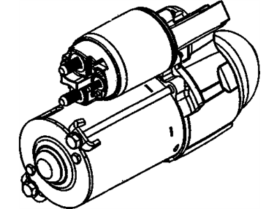
1998 Oldsmobile Cutlass Start Motor Assembly (Remanufacture)
Part Number: 10465459$112.35 MSRP: $339.90You Save: $227.55 (67%)Ships in 1-2 Business DaysProduct Specifications- Other Name: STARTER, Starter Motor; Starter
- Replaces: 10465384
- Item Weight: 8.20 Pounds
- Item Dimensions: 6.2 x 6.3 x 12.5 inches
- Condition: New
- Fitment Type: Direct Replacement
- SKU: 10465459
- Warranty: This genuine part is guaranteed by GM's factory warranty.
- Product Specifications
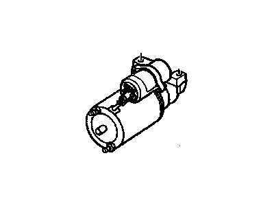
- Other Name: STARTER, Starter Motor; Starter
- Replaces: 10455069
- Item Weight: 16.20 Pounds
- Item Dimensions: 12.4 x 6.9 x 6.2 inches
- Condition: New
- Fitment Type: Direct Replacement
- SKU: 10465494
- Warranty: This genuine part is guaranteed by GM's factory warranty.
1998 Oldsmobile Cutlass Starter
We are your prime source for competitively priced and high-quality OEM 1998 Oldsmobile Cutlass Starter. We provide you with parts that will allow you to save a lot of money without sacrificing quality. All our OEM parts are backed by the manufacturer's warranty and shipped out at a swift rate.
1998 Oldsmobile Cutlass Starter Parts Questions & Experts Answers
- Q: How to reassemble and adjust Starter on 1998 Oldsmobile Cutlass?A: The brush assembly can be installed to the field frame by affixing brushes to the holders, joining the insulated and the grounded brushholders with V-spring and placing the unit on the support pin. Screw and press the holders and the spring to the bottom of the support and, as the result, rotate the spring so that it put the V over the support slot. Screw the ground wire into the extending part of the grounded brush and the field lead wire to the extending part of the insulated brush, do the same operations for the other set of brushes. Apply Silicone oil on the drive end of the armature shaft and slide the clutch assembly on the shaft in front side of the pinion. Third, insert the pinion stop/retainer over the shaft with the groove part in the direction from the pinion. The completed armature should be stood vertically on a piece of wood, the snap-ring should then be put over the end of the shaft and with the aid of a hammer and piece of hardwood this should then be driven on to the shaft. Lower the snap ring and place it under it to the groove and then fit the thrust collar around the shaft with the wider part adjacent to the snap-ring. Force the thrust collar and stop/retainer to come closer each other until you can see that the snap-ring is already seated in its proper place in the retainer. Coat the drive housing bushing with silicone oil, align the thrust collar over the snap-ring, place the armature and clutch into the drive housing and fit the gear-shift lever into the clutch. Align the field frame over the armature and use the sealing compound to fill a gap between the frame and the solenoid case and place the field frame gently onto the drive housing as doing it hard will damage the brushes. apply silicone oil onto the Bushing in the commutator End-frame the place the leather brake washer on the Armature shaft Place the commutator End-frame over the shaft. Some cotton wires are connected to the MOTOR terminal of the solenoid and there is a latch on the right that connects field coil connectors to the solenoid. To obtain the pinion clearance, connect across the solenoid S terminal, a 6 volt battery and connecting a heavy cable between the MOTOR terminal and negative terminal to make the starter static. When the current in the solenoid rises the spring force will thrust the pinion back up to the normal cranking position. This may require you to push the pinion away from the stop/retainer to take out any loose play before ascertaining proper engagement of the pinion face with the stop/retainer face, by feeler gauge, this dimension HAS to be between 0.010 INCH to 0,.140 INCH for desired engagement of with the flywheel or driveplate ring-gear. If the clearance is wrong, disassemble the starter again and change any damaged or misshaped parts, as no adjustment is possible.


