My Garage
My Account
Cart
Genuine Chevrolet Tracker Blower Motor
A/C Heater Blower Motor- Select Vehicle by Model
- Select Vehicle by VIN
Select Vehicle by Model
orMake
Model
Year
Select Vehicle by VIN
For the most accurate results, select vehicle by your VIN (Vehicle Identification Number).
5 Blower Motors found
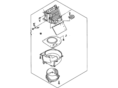
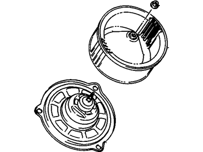
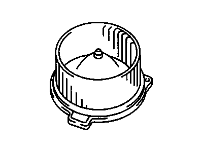
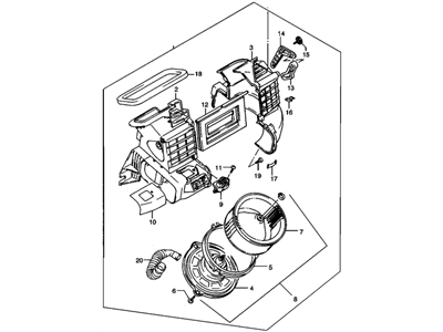
Chevrolet Tracker Blower
Part Number: 30026572$550.62 MSRP: $717.27You Save: $166.65 (24%)Ships in 1-2 Business Days
Chevrolet Tracker Blower Motor
The existence of Blower Motor in Chevrolet Tracker make it possible to blow hot or cool air inside the car's cabin. It works through supplying a fan with electrical energy that blows air inside thus providing drivers with the required temperature. The Chevrolet Tracker may use one blower motor or even more in some configurations to improve climate control of the vehicle cabin. The Blower motor and its controls must be well taken care of because when it fails, there will be no control of heating and air conditioning. There could be a problem with electronic control module, wiring, or the physical controls and when there are, it is possible to sense it. On the whole it can be said that the Chevrolet Tracker Blower Motor is a very important component when it comes to regulating the climate inside the car for the comfort of passengers.
Each OEM Chevrolet Tracker Blower Motor we offer is competitively priced and comes with the assurance of the manufacturer's warranty for the part. Furthermore, we guarantee the speedy delivery of your orders right to your doorstep. Our hassle-free return policy is also in place for your peace of mind.
Chevrolet Tracker Blower Motor Parts Questions & Experts Answers
- Q: How is the blower motor positioned and tested on Chevrolet Tracker?A:On Samurai models the blower unit is mounted above and to the right of the throttle pedal while on Sidekick and Tracker models are mounted on the dash board infront of the glove box. The blower motor unit circuit is the battery, switch on the dash mounted air conditioning or heating control assembly, resistor and relay for the 1999 and later Vitara/Tracker. To ensure that the blower motor circuit has no problem, check the fuses and connections for loose connections, or signs of corrosion and always ensure the battery is charged. Insert the T-pins to back probe the blower unit electrical connector terminals and connect the voltmeter leads to the T-pins. Turn the ignition key to the ON position and operate the blower motor switch observing the voltage variations; on shifting the switch to the higher positions the resistance will reduce the voltage will be high and blower fan speed will be high. In case the blower unit does not work, the same may be attributed to the blower speed switch. If it activates but do not increase speed, check the switch and blower resistor circuit. To check the blower unit, turn the electrical connection off and then with the ohmmeter, measure whether or not you get continuity between the two connectors on the blower motor; if there is no continuity, then replace the blower unit. If continuity is present then you have to connect the battery voltage source to the blower unit connector terminals to check the functionality. If the blower unit fails to come on the unit should be replaced; if the blower comes on when jumped and does not operate when the switch is turned on, the blower motor switch should be inspected. For Samurai models, measure continuity between the indicated terminals at each switch position using an ohmmeter or a self-powered test light no continuity at the OFF; continuity at the other positions as indicated. For Sidekick/Tracker models manufactured between 1987 and 1997, conduct continuity check, but with certain terminal sets. Continuity check Is as follows: for 1998 models, it is continuity between the terminals noted in the circuit, and for 1999 and later models, check continuity between the terminals mentioned in the circuit. To check the heater blower resistor, using an ohmmeter check the resistance between the resistor connector terminals for several models and replace the resistor if the resistance is not accurate. For the models manufactured in and after 1999, the heater blower relay must be tested for continuity on its terminals when powered. For replacements, the next step is to take out the air conditioning and heater control assembly in order to get access to the blower motor switch, blower resistor, as well as the blower unit all of which should be then installed in the reverse manner. For Vitara and Tracker models, locate and get access to the blower motor switch and resistor by first removing the glove box as for the blower unit and relay make sure that they are installed correctly.


