My Garage
My Account
Cart
Genuine Chevrolet Distributor
Ignition Distributor- Select Vehicle by Model
- Select Vehicle by VIN
Select Vehicle by Model
orMake
Model
Year
Select Vehicle by VIN
For the most accurate results, select vehicle by your VIN (Vehicle Identification Number).
22 Distributors found
- Product Specifications
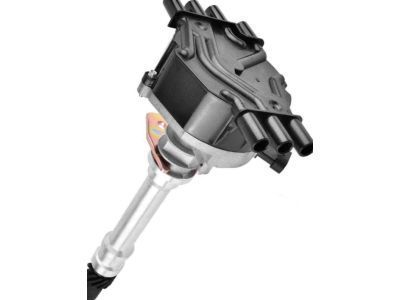
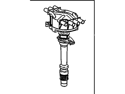
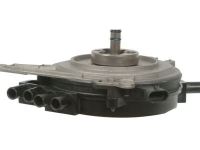
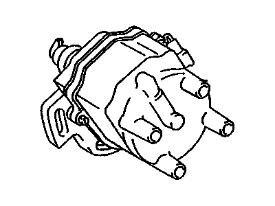
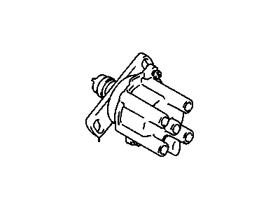
- Other Name: DISTRIBUTOR, Ignition; Distributor, Distributor Assembly
- Replaces: 01104057, 01104078, 01104050, 1104050, 1104078, 1104057, 93441559
- Product Specifications
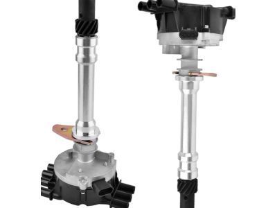
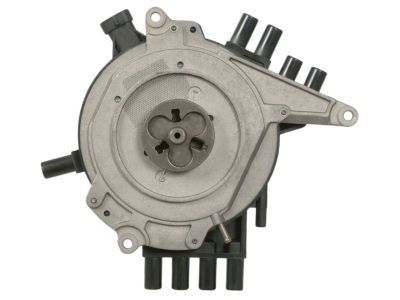
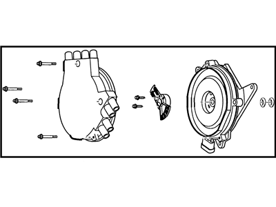
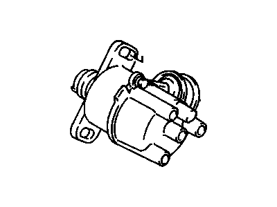
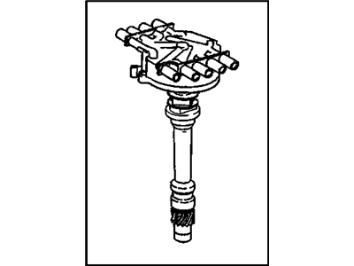
- Other Name: DISTRIBUTOR, Ignition; Distributor, Distributor Assembly
- Replaces: 01104032, 1103916, 1104032
- Product Specifications
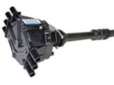
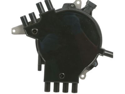
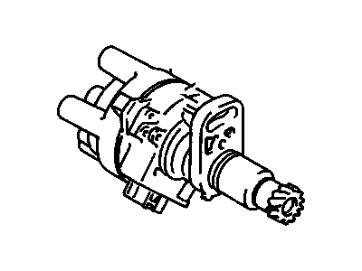
- Other Name: DISTRIBUTOR, Ignition; Distributor
- Product Specifications
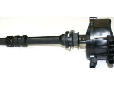
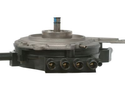
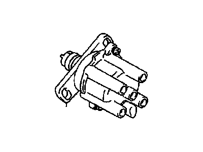
- Other Name: DISTRIBUTOR, Ignition; Distributor Assembly
- Product Specifications
- Other Name: DISTRIBUTOR, Ignition; Distributor, Ignition Assembly
- Product Specifications
- Other Name: DISTRIBUTOR, Ignition
- Product Specifications
- Other Name: DISTRIBUTOR, Ignition
- Product Specifications
- Other Name: DISTRIBUTOR, Ignition
- Product Specifications
- Other Name: DISTRIBUTOR, Ignition; Distributor Assembly
- Product Specifications
- Other Name: DISTRIBUTOR, Ignition
- Product Specifications
- Other Name: DISTRIBUTOR, Ignition
- Product Specifications
- Other Name: DISTRIBUTOR, Ignition
- Product Specifications
- Other Name: DISTRIBUTOR, Ignition
- Product Specifications
- Other Name: DISTRIBUTOR, Ignition; Distributor Assembly
- Product Specifications
- Other Name: DISTRIBUTOR, Ignition
- Product Specifications
- Other Name: DISTRIBUTOR, Ignition; Distributor, Distributor Assembly, Starter
- Replaces: 01104058, 01104051, 01104079, 1104058, 93441558, 1104079, 1103977, 1104051, 12570425
- Product Specifications
- Other Name: DISTRIBUTOR, Ignition
- Product Specifications
- Other Name: Ignition Module; Igniter
| Page 1 of 2 |Next >
1-20 of 22 Results
Chevrolet Distributor
At GMPartsGiant.com, we offer an extensive inventory of genuine Chevrolet Distributors at competitive prices in the market. All our OEM Chevrolet Distributors are backed by the manufacturer's warranty and will be shipped promptly to your doorstep. Rest assured, our hassle-free return policy is designed to support you throughout your shopping experience!
Chevrolet Distributor Parts Questions & Experts Answers
- Q: How to overhaul the HEI type distributor on Chevrolet Nova?A:To check the pick-up coil, one has to take out the distributor and then the rotor to do it. Then open the tap module by pulling and taking out the two screws of this module, then move the module aside and remove the connection from the '8' and 'C' terminals, then connections from the 'W' and 'G' terminals. Gently expand the roll pin from the drive gear and finally, the gear, shim and the tanged washer will have to be withdrawn from the distributor shaft. Before pulling the shaft out of the housing, make sure that it is not caked, and remove the washer from the upper end of the distributor housing. Slide off the retaining ring for removal of the pick-up coil and pole piece; this can be done after employing the screw driver to pry out the 'C' clip. The vacuum unit can be detached by unscrewing two screws, then you can take out lock ring, pick-up coil retainer, shim and felt washer. Ground the capacitor lead and remove the capacitor with one bolt, then, the wiring harness from the distributor housing. Wipe all parts with a cloth that has a solvent on it and look for any signs of deterioration or damage and replace when needed. In assembly, there should be the vacuum unit that should be placed at the housing and fixed with two screws. Install the felt washer over the lubricant reservoir on top of the housing then the shim should be placed on top of the felt washer. Place the pick-up coil and pole-piece assembly in place and secure it back into the vacuum advance arm and place the retaining ring on. The washer must be fitted into the top of the housing while the distributor shaft should be fitted and then measure equal distances to the pole piece projections. Fit in the tanged washer, shim and drive gear and make the gear coincide with new roll pin. Finally screw the capacitor halfway in and snap the connector to the 'B' and 'C' terminals of the module and the tab must be at the top. 2 Insert the module into the base with silicone grease applied at the base of the module in order to make a good heat conduction and use two screws. Insert the wiring harness into the housing with the grommet added to the housing notch, then bring the pink terminated wire to the capacitor stud and connect it with the screw for the capacitor while tightening the black wire terminated to the capacitor mounting screw. Fix the white wire to module 'W' and the green wire to 'G' of the pick-up coil. Last, place the advance weights, weight retainer (dimple down), and springs and fasten the rotor with two screws so that the side notch of the rotor fits the tab situated on the base of the cam weight, and then the distributor.
- Q: How to measure and adjust the air gap in a distributor on Chevrolet Metro?A:Turn the engine off and then, using your wrench or your hands, unscrew the distributor cap and the rotor from the engine. With a feeler gauge, ascertain the clearance between one of the teeth of the pole piece and the pick-up coil, on a vacuum / centrifugal advance distributor. If at all you are handling an electronic spark control distributor, it is advisable to measure the gap between a ridge of the signal rotor and the generator assembly. Measure the air gap with the help of a caliper, and take the value from the specifications manual. If this is so with the air gap, then the electical technician may have to correct the position. In order to change the air gap on a vacuum/centrifugal advance distributor you should first remove the module/igniter and then unscrew the two screws which are typically mounted behind the pick-up coil. Slide the pick-up coil assembly till the gap is ideal and tighten the screws again. For the electronic spark control distributor the generator assembly can be adjusted by loosening the retaining screws for the spark gap. Using a screwdriver make the distance between the pick-up coil/generator assembly to come with in specified range the screws are tightened and checked for its gap again. Place the module/igniter if available, the rotor and the distributor cap.
- Q: How to remove the distributor on Chevrolet Tracker?A:To remove the distributor, start by unplugging the distributor primary lead wire from the coil and disconnecting the electrical connector for the igniter. Locate the number one cylinder spark plug wire terminal by looking for a raised "1" on the distributor cap or tracing the wire back from the number one spark plug. Remove the distributor cap and position the rotor to point at the number one spark plug terminal. Make alignment marks on the distributor body, gear case, and distributor coupling (for 1996 models). Remove the distributor hold down bolt and clamp, then pull the distributor straight out. When installing the distributor, ensure it is inserted in the same position as before and mesh the helical gears by turning the rotor slightly. Check the alignment marks and rotor position, then place the hold down clamp and loosely install the bolt. Install the distributor cap, plug in the electrical connectors, reattach the spark plug wires, and connect the battery cable. Finally, check and adjust the ignition timing as needed.
Related Chevrolet Parts
Browse by Model
Astro Distributor Blazer Distributor C1500 Distributor C2500 Distributor C3500 Distributor Camaro Distributor Caprice Distributor Corvette Distributor Express Distributor Impala Distributor K1500 Distributor K2500 Distributor K3500 Distributor Metro Distributor Nova Distributor P30 Distributor Prizm Distributor S10 Distributor Silverado Distributor Sprint Distributor Storm Distributor Suburban Distributor Tahoe Distributor Tracker Distributor
